
ANO LED fidget toy
- Arrives in 2 to 7 business days Printed in Auckland. $10 shipping, free over $75
- 14-day faulty refund If it arrives broken or misprinted, we reprint or refund it
- Secure checkout Card payments handled by Stripe
- Material
- High-Detail Resin (8K)
- Colour
- Grey
- Weight
- ~50 g
- Print time
- ~2.8 h
- Express shipping
- $20
More information
Updated (January 27 2024)
• Added a version of the case bottom specifically for the Feather RP2040, which includes a cutout for a power button, and slightly differently spaced holes for the back part of the mount. • Included a version of the case for ESP32-S2/S3 Feathers with a power button cutout. • Added a version of the LED mount/platform with geometry to hold the power button in place. • Adjusted the grid and case top geometry to extend the friction fit part of the case top by 1mm.
Overview
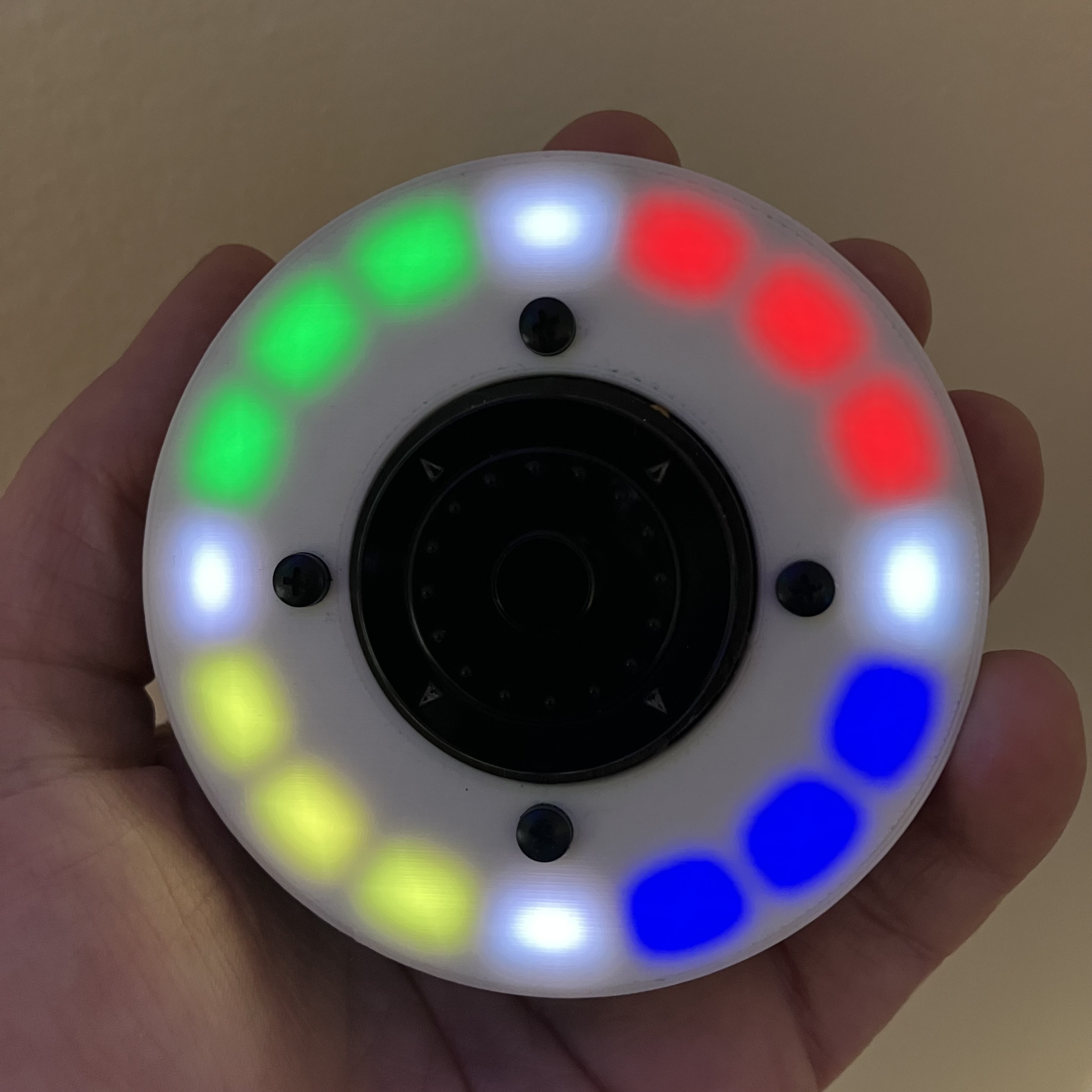
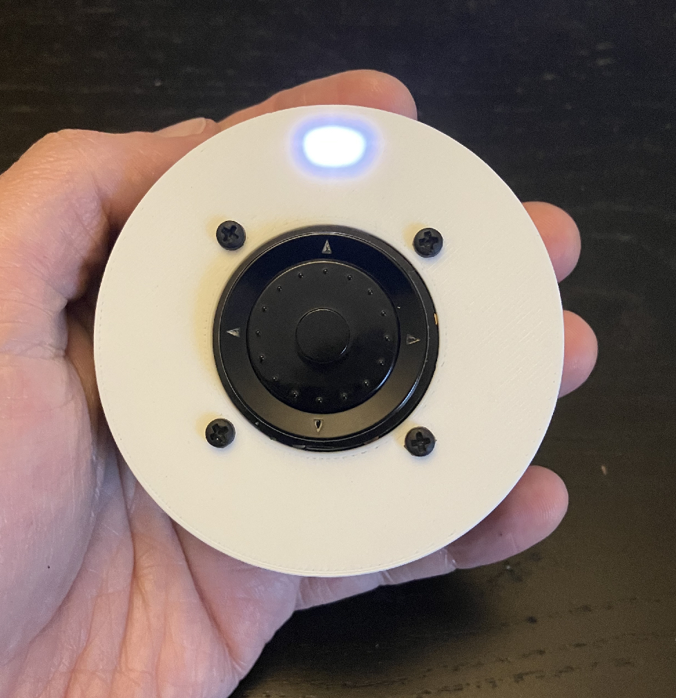
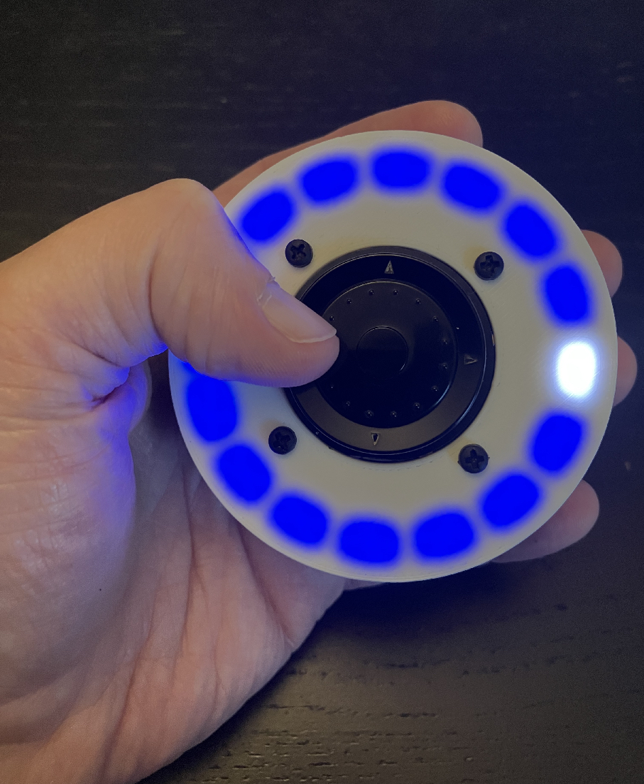
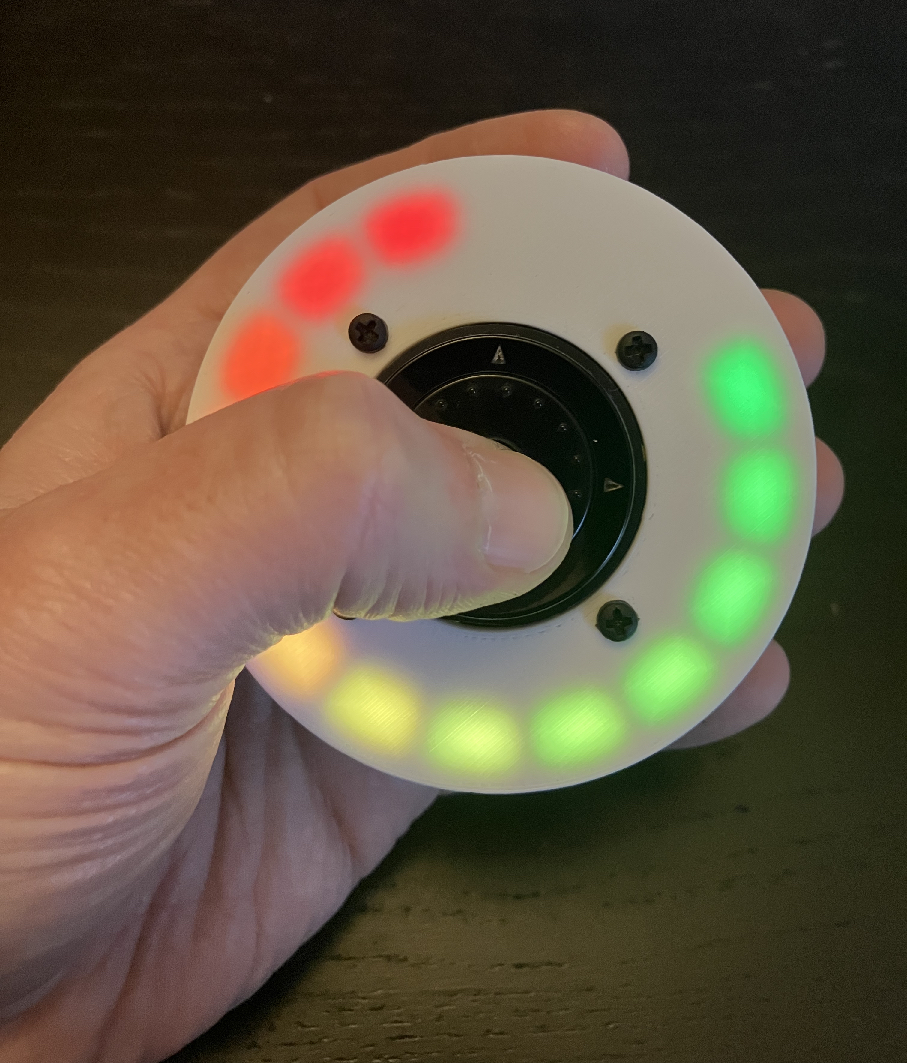
A rotary-encoder-based “fidget” toy, inspired by this project. Uses an ANO directional navigation and rotary encoder (and breakout board), an LED ring with 16 LEDs, a Feather microcontroller, and a 400 mAh battery. ANO control is mounted to the case lid with screws and nuts, and the lid is friction-fitted into the case bottom.
Recommended Feathers
The recommended build is to use a Feather RP2040 with a power button. Please visit https://adafruit-playground.com/u/squid_jpg/pages/custom-ano-fidget-firmware for a write-up on some custom CircuitPython firmware designed for devices featuring a power switch. The firmware features multiple fidget modes and a variation of the popular Simon electronic game.
If using a Feather ESP32-S2/S3, this build can also double as a WiFi remote control.
3D printed parts
You'll need to print a total of 4 parts. Which parts you print depends on which Feather you choose and/or whether you are using a switch to toggle power.
• Case bottom: • Feather RP2040: • rotary-fidget-toy-case-bottom-power-button-rp2040.stl
• Feather ESP32S2/S3: • With power button: rotary-fidget-toy-case-bottom-power-button.stl • Without power button: rotary-fidget-toy-case-bottom.stl
• LED Mount/Platform • With power button: rotary-fidget-toy-led-ring-platform-power-button.stl • Without power button: rotary-fidget-toy-led-ring-platform.stl
• LED Grid • rotary-fidget-toy-led-ring-grid.stl
• Case top: • rotary-fidget-toy-case-top.stl
##
Print settings
• Material: PLA • Layer height: 0.2mm • I used white and black filament for the top of the case, and black filament for everything else. When slicing the case top/lid, print the main top part in white, and change filament to black after 2.0 mm.
Supports
• LED Grid: For best results, flip upside down and use supports when slicing. • Case bottom: You might need to use supports due to the rounded bottom. • All other parts can be printed without supports.
Notes
• If using a power switch, wire one end of the switch to the EN pin of the feather, and the other to GND. When switched into the “off” position, the 3v3 regulator will be powered down, along with everything connected to it. You'll want to power the LED ring via the 3v3 pin so that the LEDs shut down as well when the power is disabled. • The simplest way to build this device is to use a power switch. However, if you're using the Feather ESP32-S2 or -S3, you have the option to omit the power switch, and use deep sleep mode (waking with any of the buttons). In order to achieve the lowest possible power consumption (without additional hardware), while still allowing the use of I2C devices, (such as the built-in battery monitor) it is necessary to power the LED ring using the Feather's Stemma QT port, with the LED data pin connected to a non-I2C GPIO on the Feather. Then, before going into deep sleep, power to the port should be toggled off programmatically, cutting power to the LEDs. Instructions/BOM for the cables are in the Minimal Power Consumption during deep sleep section at the bottom. If you decide to use a physical switch, none of this is necessary, as you can simply use the switch to power the device on/off. • A “blank” version of the case bottom with no mounting geometry or USB cutout is included to make it easier to remix to use your own microcontroller. • A custom model of the LED ring from the BOM is included in the 3D files.
BOM
• Adafruit Feather board. I've tested so far with: • Adafruit Feather RP2040 • Adafruit Feather ESP32-S2 • Adafruit Feather ESP32-S3
• 16-LED ring (make sure to choose the “16-bit” ring!) • ANO Directional Navigation and Scroll Wheel Rotary Encoder • ANO Breakout PCB • 400 mAh LiPo battery (though there is probably room for a larger battery if desired, you'll have to experiment). If you don't get your battery from Adafruit, MAKE SURE THE POLARITY MATCHES THE CONNECTOR ON THE FEATHER! • On/off button • 4 2.5M heat sink insets (inserted into the holes on the Feather mounting geometry) • 4 nylon 2.5M 6mm long screws (for attaching the Feather to the mount geometry • 4 nylon 2.5M screws, at least 8mm long (for attaching the ANO breakout to the case top) • 4 nylon 2.5M nuts
Minimal power consumption during deep sleep (ESP32-S2/S3 only)
For lowest power consumption during ESP32 deep sleep, you'll need to make a patch cable that converts from a 4-pin Stemma QT cable + Feather GPIO to a 3-pin male connector, and solder a female 3-pin connector to the LED ring. This also makes it easier to connect/disconnect the LED ring and even replace it in the future if necessary. Note that we're soldering silicone wires to the PVC wires of the connectors for strain relief. This makes them much more resilient and less likely to break when you stuff them inside the case. You'll need:
• Stemma QT/4-pin JST SH cable (or any cable with at least 1 female connector) • 3-pin male and female JST PH connector pair • Some silicone wire, 26-28 AWG is fine since we're not carrying much current. You'll want 2 red pieces, 2 black pieces, and 2 yellow (or green, or blue, or whatever) pieces, all cut to about 3-4 cm. • Heat shrink tubing
Build and solder the connectors
• Build the adapter connector cable for the feather • Carefully cut/pull out the blue and yellow wires from the 4-pin Stemma QT female connector. • Snip off the remaining red and black wires from the Stemma QT cable leaving about 3-4 cm of wire attached to the connector. • Trim about 2-3 mm of insulation from the red and black Stemma QT wires, and trim 2-3 mm of insulation from one end each of one of the red and one of the black silicone wires. • Solder the red and black cables from the 4-pin connector to the trimmed pieces of the red silicon wire and black silicon wire, respectively. • Cut 2 pieces of heat shrink tubing to about 1 cm, slide it over the solder joints of the wires you just soldered, and heat up the tubing to shrink it and insulate the wires. • Trim and solder one end of the yellow silicon wires to whichever GPIO on the Feather you want to use to drive the LED ring. • Cut 3 more pieces of heat shrink tubing about 1 cm each and slide them over the red and black silicon wires connected to the 4-pin connector, and slide the remaining one over the yellow wire connected to the Feather GPIO. • Snip off the wires from the 3-pin male JST connector leaving about 3-4 cm of wire attached to the connector. • Trim and solder the 3-pin connector wires to the silicon wires attached to the microcontroller, soldering the red wires together, the black wires together, and the yellow wires together. • Slide the heat shrink tubing you put on the wires in step 7 over the solder joints and heat to insulate. • Plug the 4-pin Stemma QT connector into the Stemma QT port of the Feather.
• Build and solder the connector cable for the LED ring • Trim about 2-3 mm of insulation from one end of each of the remaining pieces of red, black, and yellow silicone wires. • Solder the red silicon wire to the 5V pin on the LED ring, the black silicone wire to the GND pin, and the yellow wire to the DI pin. • Trim 2-3 mm of insulation from the other ends of the silicon wires you just soldered to the LED ring. • Snip off the wires from the 3-pin female JST connector, leaving about 3-4 cm of wire attached to the connector, and trim about 2-3mm of insulation from each of the wires. • Cut 3 pieces of heat shrink tubing, each about 1 cm, and slide each one over the wires soldered to the LED ring. • Solder each of the wires from the 3-pin connector to the LED ring. • Slide the pieces of heat shrink tubing from step 5 over the solder joints on the wires, and heat to insulate.
Finally, you can plug the 3-pin female connector from the LED ring into the 3-pin male connector attached to the Feather, and your LED ring will be powered using 3.3v from the Stemma QT port. Power to the Stemma port can be toggled on/off in code.
Design and description by squid.jpg , licensed CC-BY-SA.
Frequently asked
How long does shipping take?
ANO LED fidget toy is printed to order. Lead time is typically 1-3 business days plus 1-4 days NZ shipping. Standard NZ shipping is $10, free over $75.
What material is this printed in?
By default this is printed in High-Detail Resin (8K) at 0.025 mm layer height on an MSLA resin printer. Custom material and colour swaps are available, just leave a note at checkout.
Can I get this in a different colour?
Yes. Every product can be printed in any of the resin colours we stock, or hand-painted on request. Leave a note at checkout or email [email protected].
Do you ship outside of New Zealand?
Currently New Zealand only. Australian shipping is coming.
Who designed this?
Designed by an independent sculptor and licensed for commercial printing. The original is linked on this page.